The
thrill, glory, excitement, adrenaline rush, late nights, sore
eyes, cuts, bruises, frozen gray matter, growling stomach,
goose bumps, debugging, coding-recoding, learning-relearning,
yelling, shouting...........this is what micromouse does to
you. I experienced it all. It really gets on to you. I know
I sound like a complete fanatic, but that’s just me.
I
have been working on and off on this project for the last
two years. With one failure already under my belt, this one
was going to be my last ditch effort. Remember the time when
you want to pee real hard and there’s no toilet in sight
and then you wait n wait but cant hold it back no more and
then you decide to let it go on a side walk? ever experienced
that magical moment? That’s exactly what happened to
me. Our mouse didn’t make it to the center of the maze,
but did manage to fetch us a third prize for our efforts.
The story goes something like this...
Not
exactly a story, rather a documentation filled with experimentations
and learning experiences that you might find useful. It begins
with an anatomy.
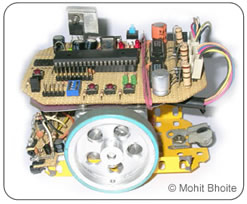
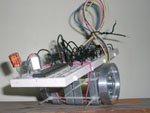
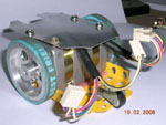
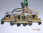
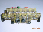
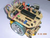
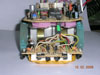
Chassis
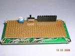
The prototype chassis consisted of nothing more
than two motors held together by nylon ties and the breadboard
simply mounted on top of it. It was ideal for testing out
small motor driving routines. After the motors were finalized,
I decided to build the final chassis. It was built using a
combination of aluminum sheet and mechano base plate. The
end result was very robust and flexible.
The
Motors
The selection of motors was the most time consuming
part of the whole project. I worked on different motors for
months, trying to figure out an ideal torque to weight ratio.
I am lucky to live in Mumbai, the home to the Lamington road.
A place where you can find almost anything and everything
related to electronics. Stepper motors are available in plenty
over here but most of them are ex-stock or come out of old
electronic gadgets. Nonetheless they are more than sufficient
for our needs.
While
choosing a stepper motor for a micromouse, one must keep a
few things in mind. First, you need to look for motors with
low voltages and higher current ratings. Secondly look for
a Nema17 size motors, it means that they should have a width
x height of 1.7 x 1.7 inches. This holds true for unipolar
as well as bipolar motors.
After
a 3 month long search, I narrowed down on a lovely pair of
unipolar motors, although not an ideal choice, they were pretty
close. Rated at 4.5Volts 450mA, these babies were just begging
to be over-driven.
Bombay Electronics
Servo
Electronics
Our
motors from Servo
At
lamington road, there are two popular places where you can
hunt for your dream motors, Servo Electronics and Bombay Electronics,
Servo being the leader in variety.
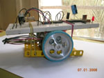
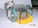
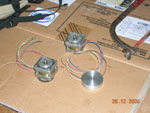
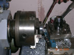
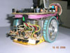
Wheels
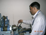
We have a beautiful lathe machine in our college
workshop. And the operator is an experienced perfectionist.
So the wheels turned out to be a cake walk. The end result
is yours to see. They were fabricated out of solid aluminum,
a bit on the expensive side, Rs.150 each.
Recently
there has been a craze to wear friendship bands all across
Mumbai. The day I saw one guy wearing it, I knew I had found
a ‘perfect’ match for my wheels. I mean, these
bands are awesome, you simply can’t find a better ‘tyre’.
They are available in all sorts of colours and cost about
Rs.15 to 25 each, now beat that!
Power
Supply
Our micromouse was driven by a pack of 10 AAA
Ni-Cd (600mAh) cells. Maybe this was one of the first mistakes
we made. We should have chosen AA size Ni-Mh cells or maybe
lithium-ions. Our batteries simply drained out in a matter
of minutes.
But
on the other hand I was using a MAX727 switch mode regulator
with a peak efficiency of 90%. It proved to be a far better
option than a 7805.
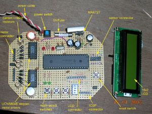
The
Brain
I have always felt at home while using PIC microcontrollers.
PIC 18F452 is a very powerful chip and is supported by Microchip’s
C18 C compiler. So there were no second thoughts when it came
to choosing the brain. Micromouse demands a lot of processing
power, a good onboard ADC and lot of multiprocessing tasks
(good set of timers), this PIC has got it all. Although there
is no free running ADC mode, the actual conversion time is
really small, somewhere around 13us.
Many
of the mice that I see here in India are based around ATMEL
microcontrollers. I never used them myself, so can’t
talk more on that. But after reading a few encouraging posts
on local forums, I have begun to think that maybe I should
give atmels a try, maybe in my forthcoming projects? For now,
PICs rock!
18F452
fact sheet:
Flash
Memory
32k
RAM
1.5k
EEPROM
256bytes
Max
clock frequency
40Mhz
(10x4)
PWM
channels
2
10
bit ADC channels
8
Timers
4
I2C,SPI,USART,PSP
yes
In
Circuit Serial Programming (ICSP)
yes
Sensors
I decided to use side-looking sensors to measure
the distance from the wall and to detect their absence/presence.
Compared to the top-down looking arrangement, the side-looking
arrangement is harder to implement, but on the brighter side,
it makes the whole design compact >> higher speeds.
I
knew that the sensors were going to be the most critical of
all the systems in this micromouse. The whole fate of the
project relied on them. There are three popular methods of
distance measurement, use of readymade distance measuring
modules (Sharp’s GP2D120), use of IR led-phototransistor
pair or using visible red led-phototransistor pair. (ultrasonics
can also be used, but are severely limited by their slow sampling
rates) Sharp’s modules are expensive and using visible
red LEDs required modulation, so I eventually settled down
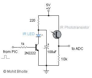
on using IR led-phototransistor pair.
There
are a variety of sensors available in the local market today,
choosing the right one is a daunting task. I located a dealer
here in Mumbai, who solely deals in IR sensors; on his recommendation
I bought 4 sensor pairs for Rs.20 each. The ultra bright IR
LED was enclosed in a clear 3mm plastic package while the
phototransistor was enclosed in a 3mm darkened plastic (to
filter out the visible light)
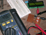
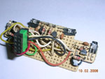
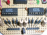
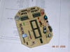
I
used a simple circuit arrangement as shown below. Static breadboard
testing results were encouraging and they gave a range of
about 1cm to 9cm, which was just about enough.
To
test the circuit, I connected the sensor output to one of
the ADC pins of 18F452 which followed a code that subtracted
the ambient light value from the readings and dumped the result
on a 2-line LCD.
Everything
was going smoothly, until that unfortunate but inevitable
moment. ADCs are very sensitive to even the slightest of voltage
fluctuations. Now imagine placing them on two electromagnetically
active, current sucking monsters, ‘the stepper motors’.
I had a very hard time dealing with this notorious couple.
I tried spraying capacitors all around them, but no significant
improvements were in sight. With the competition day at my
door-step, I had no option but to move on. The only logical
solution was to use two separate batteries, one for the electronics
and the other for the motors. (Just good enough)
I
wondered how the Japanese or the Singaporeans managed everything
with a single battery. I guess it’s all about designing
a good PCB (placing the digital and analog grounds miles away
from each other). Ok, so I didn’t get it right the first
time, but hey, there’s always a next time, right?
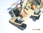
The
final sensor arrangement looks something like this:
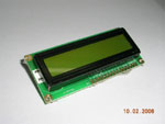
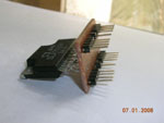
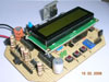
LCD
LCD is an extremely handy debugging tool. Microchip’s
C18 compiler has inbuilt LCD libraries; you have to be a fool
not to use them. I built a pluggable module out of a 16x2
LCD that has a contrast-setting pot and a backlight switch
soldered on to the back.
I
used the LCD for two main purposes:
I wrote a small routine that displayed all the sensor readings
continuously/triggered, on the LCD. So that I could observe
and note the readings as I manually moved the mouse through
the maze.
A
second routine allowed me to set the number of steps required
to travel a distance of one cell, or turn by 90/180 degrees.
Using three switches (to increment, decrement and select the
number of steps}, I was able to accurately determine and set
newer values on the mouse itself, instead of re-programming
the chip all the time.
Heres
a sample code for the ADC routines:
void
read_sidesensors(void)
{
siderightled=0; //
initially both IR LEDs are turned off
sideleftled=0;
//Read
side right sensor value//
SetChanADC( ADC_CH0 );
ConvertADC( ); //
Start conversion
while( BusyADC ( ) ); //
Wait for completion of ADC
ambientright = ReadADC( ); //
Read ambient value with LED OFF
siderightled=1; //
turn on the IR LED
Delay10TCYx( 6 );
// wait for LED to glow fully
ConvertADC( ); //
Start conversion
while( BusyADC( ) ); //
Wait for completion of ADC
rightirvalue=ReadADC( ); //
Read value with LED turned ON
siderightled=0; //
turn off the LED
rightvalue=rightirvalue-ambientright; // calculate the 'clean' value
//Read side left sensor value//
SetChanADC( ADC_CH1 );
ConvertADC(); // Start conversion
while( BusyADC( ) ); //
Wait for completion of ADC
ambientleft = ReadADC( ); //
Read ambient value with LED OFF
sideleftled=1; //
turn on the IR LED
Delay10TCYx( 6 ); //
wait for LED to glow fully
ConvertADC( ); //
Start conversion
while( BusyADC( ) ); //
Wait for completion of ADC
leftirvalue=ReadADC( ); //
Read value with LED turned ON
sideleftled=0;
// turn off the LED
CloseADC( );
leftvalue=leftirvalue-ambientleft; // calculate the 'clean' value
//Calculate
their difference//
difference = rightvalue-leftvalue;
return;
}
//Displays
the ADC result on to the LCD display//
void display_sidesensors(void)
{
OpenXLCD( FOUR_BIT & LINES_5X7
); //configure
LCD
while( BusyXLCD() );
putrsXLCD("Side: ");
while( BusyXLCD( ) );
itoa(leftvalue,string1 );
//converts the ADC int value into a string
putsXLCD(string1); //Display
the left ADC value on the LCD
while( BusyXLCD( ) );
putrsXLCD(" ");
while( BusyXLCD( ) );
itoa(rightvalue,string2 ); //converts
the ADC int value into a string
putsXLCD(string2); //Display
the right ADC value on the LCD
while( BusyXLCD( ) );
return;
}
Motor Drivers
To get the maximum performance out of any stepper
motors, you need to overdrive them, that is, increasing the
supply voltage while limiting the current to the rated levels.
To overdrive my motors, I supplied a voltage of 12 volts (rating
was 4.5Volts) and limited the current to the rated 0.45Amps.
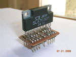
Current chopping is an ideal way to do this. I had used UCN5804
uni-polar driver chip, from Allegro Micro, in my earlier failed
attempt of building a micromouse. These chips have an inbuilt
translator and driver but no current chopping facility. So
I turned my attention in search of some fancy current chopping
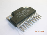
chips. A quick search revealed SLA7832 as an ideal candidate.It
seemed that this chip had got it all, except for the translator.
After a long frustrating search at lamington road, I finally
managed to locate a shop which had box full of such chips.
(Bought two of them for Rs.200 each)
These
chips are very difficult to test (“difficult”—
a complete understatement). They are not meant for bread-boarding
at all, so I had to make an adapter for them. After hours
and days of testing, I simply couldn’t get them working.
I tried every possible circuit arrangement, but no result.
I seriously believe that I was duped. At Rs.200 per chip,
they must have been the duplicators delight.
So
after the “pain in the a**” realization, I returned
to my left-overs, the UCN5804s. With no current chopping at
hands, I had to follow the old school method of using resistors
to limit the current. Calculations revealed that I would need
somewhere around 10ohms rated at 5watts!
The Software
Life has been good to me ever since I switched
over to C from assembly. Coding felt just like a cool breeze
through my hair. But coding for micromouse on the other hand,
turned out to be turbulent. Extreme, I love that.
I
soon realized how unpolished my coding skills were, I guess,
being an electronics engineer, the college never really encouraged
programming at higher levels. So I had to turn to my friend,
Sachin, a programming wizard. After long evenings talking
over Gtalk (he lived 1329 Kms away in Chennai), Sachin soon
came up with an elegantly written maze solving micromouse
simulator that ran on Linux. Visit his
site to know more about it.
I still had to manage the major chunk of the software that
dealt with multitasking of motor driving routines, ADC conversions,
mapping, turns, etc.
The algorithm goes something like this:
Initialization
A timer is initialized that ticks at regular intervals.(changing
the tick time period changes the speed of the motors)
At each tick, an interrupt routine is executed.
The interrupt routine consists of several sub-routines that
take care of:
Generating steps for the stepper motors
{
Generate 20us pulse for right
and left stepper motors.
If required skip a step of the
particular motor to align the robot.
Count the number of steps (distance
traveled) and call mapping function after reaching the center
of each cell.
}
Reading
the sensors
{
Read the sensors one at a time
with the IR led kept off (ambient light)
Read the sensors one at a time
with the IR led kept on
Subtract the two readings to
get a clean (almost clean) distance value.
Calculate the difference between
right and left sensor
{
If mouse is
too close to the right wall then skip a step for left motor
If mouse is
too close to the left wall then skip a step for right motor
Else no skipping
}
}
Mapping
and storing the wall information
{
Note: this part of the code
still remains undeveloped; on the day of the competition we
simply followed a depth first
search algorithm. I wanted to utilize Sachin’s simulator
code but the time was against me.
}
Right
and Left turns
180 degree turns
LCD routines to display ADC values
The
algorithm is very crude. It has desperation written all over
it. But that is exactly what happens in a 'compressed' learning
phase. I know I got miles to cover before I make it to the
center.
[click
to enlarge]
Thanks to: Sachin Surendran: for the constant encouragement,
healthy criticisms and the wonderful micromouse
simulator. (also for his promise to fund this project
someday)
Akshay
Joshi: My team mate, for all the equipments that
he provided/bought and the early morning phone calls.
Ronak
Vasa: My other team mate, for the brainstorming coding
sessions and for his ‘precious’ PIC microcontrollers.
Mr.
Narkar: our college workshop incharge, for fabricating
the beautiful pair of wheels.
Google:
for the wonderful Gtalk.
Ashish
Bhat: for proving that a world class micromouse can
indeed be built using locally available (sometimes imported)
components. His site can be found here.
And
to the IIT Techfest
team for pulling off awesome technical festivals, year after
year.
Conclusion:
You can never really explain the excitement of
building robots. Micromouse is way up in this category. If
there’s anything that I would like to tell you, it’s
this: “If you wish to build a micromouse, start right
now!”